DCVG, ACVG, PCM and CIPS Pipeline Surveys
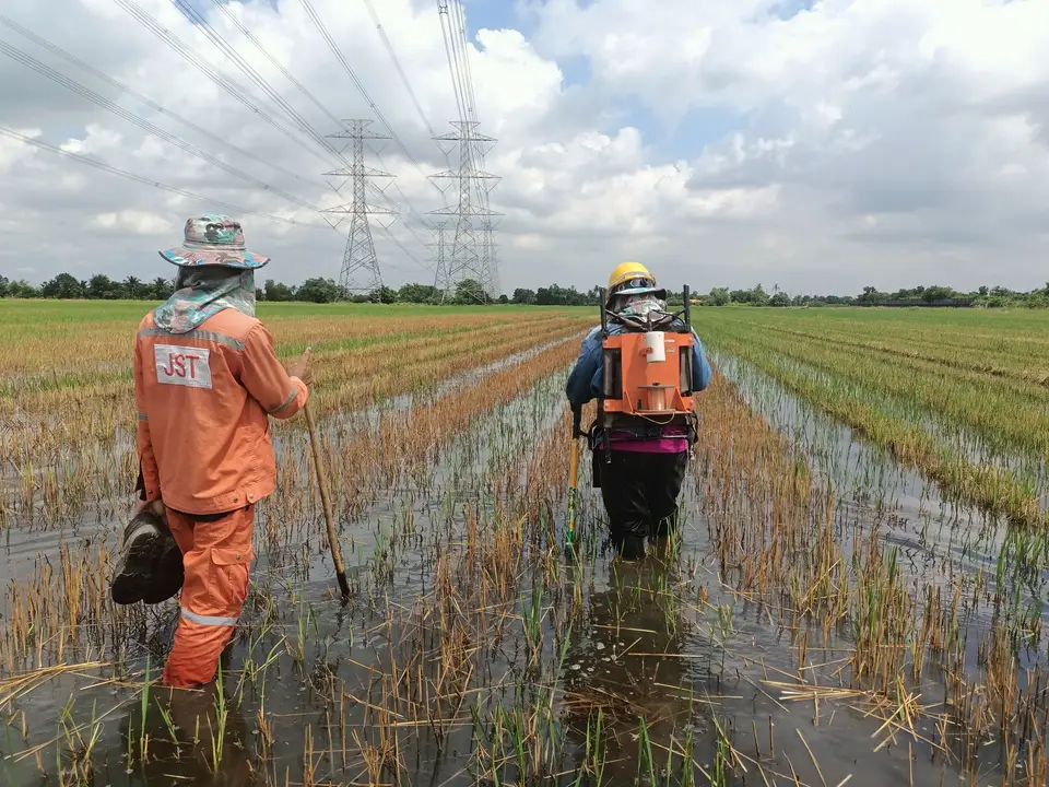
Find coating defects and cathodic protection gaps before they become leaks. Our field crews walk the line, identify, locate and grade coating defect indications, map signal current along the route, assess your CP system's performance and hand you a prioritised repair list.
Which survey do you need?
Coating and cathodic protection work as a pair. The coating keeps the soil off the steel; CP helps protect exposed steel wherever the coating has failed. Our surveys check both, and most programmes combine two or more of them.
DCVG
Direct current voltage gradient
Locates coating defects on buried pipelines and grades how severe each one is.
- Pinpoints coating defect indications
- Ranks coating defect size and shows whether each defect is likely to be corroding
- Finds interference from third-party CP systems and cable faults
Best for: Impressed-current, sacrificial-anode or unprotected lines (using a temporary rectifier where needed), and prioritising coating repairs
ACVG
Alternating current voltage gradient
Finds coating defects using an AC signal from its own transmitter, so no CP system or rectifier is needed.
- Works with or without CP, and is less affected by DC interference
- Can be run offset from the line, beside roads and in high-voltage corridors
- Pairs with PCM: PCM finds the leaking section, ACVG pinpoints the defect inside it
Best for: Sacrificial-anode or unprotected lines, urban routes and power-line corridors
PCM
Pipeline current mapping
Applies a low-frequency AC signal to the pipe and measures how much of it remains at each point along the route. Where the current falls away, the coating is leaking.
- Maps signal current along the line; a sharp drop between readings marks a section with coating damage
- Locates the pipe and reads its depth at the same time, useful where drawings are old or incomplete
- Screens long sections quickly; the ACVG A-frame then pinpoints each defect within the section
Best for: Long or poorly documented lines, unprotected or sacrificial-anode lines, and congested sites with foreign pipelines, where few contractors can offer it
CIPS
Close interval potential survey
Measures pipe-to-soil potential every 1–3 m along the whole route to assess the performance of the CP system.
- On and Off potentials with synchronised current interruption
- A GPS-tagged profile of the entire line, not just test points
- Onshore on foot; offshore and river crossings from a survey boat (On potentials only where anodes are welded to the pipe)
Best for: Verifying CP compliance, ECDA programmes, and before and after CP upgrades
Above ground, non-intrusive, no shutdown
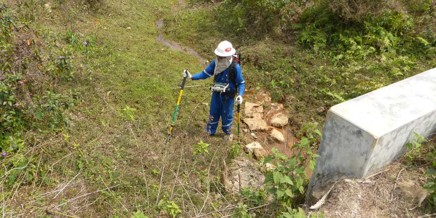
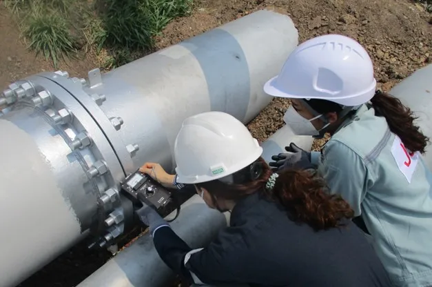
On land, all four surveys are carried out by walking the pipeline route with calibrated instruments. Nothing is excavated until the data shows exactly where to dig.
Cross-country, urban and inside the plant fence
Our crews survey cross-country transmission lines, gas distribution in towns and cities, and complex buried pipework inside refineries, petrochemical plants and tank farms. Offshore and near-shore lines are surveyed by boat, with reference electrodes towed above the pipe.
- Readings and defects logged against GPS
- Synchronised interruption of all influencing CP sources, reducing voltage-drop (IR) errors for true polarised “Off” potentials
- Surveys carried out by fully trained, experienced crews under ISO-certified processes
Advanced qualifications. Expert oversight.
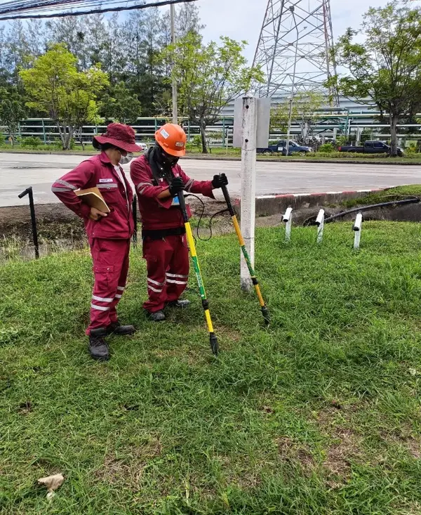
JST's corrosion-control and pipeline survey services are supported by professionals holding advanced NACE/AMPP certifications, including:
Survey work is planned, supervised and technically reviewed by these professionals, who also carry out field surveys where required. Their involvement helps ensure that the right methods are used, results are reliable and recommendations rest on sound engineering judgement.
The difference is the expertise behind every survey.
- CP Level 4 Cathodic Protection Specialist
- CP Level 3 Cathodic Protection Technologist
- Senior Corrosion Technologist
- Corrosion Specialist
DCVG, ACVG, PCM and CIPS at a glance
| Category | DCVG | ACVG | PCM | CIPS |
|---|---|---|---|---|
| Main question | Where is the coating damaged, and how badly? | Where is the coating damaged? | Which sections of coating are leaking current? | How is the CP system performing? |
| Signal source needed | An interruptible DC source: your CP rectifier, or a temporary one we install | None: its own AC transmitter | None: its own transmitter at a test post or valve | Your CP system, interrupted for polarised Off readings; none for native or depolarised surveys |
| Defect location | Direct indication of location | Direct indication of location | Section between readings; ACVG then pinpoints | Indirect (low-potential zones) |
| Defect severity | Yes (%IR and corrosion state) | Relative size | Relative, from current loss per section | No |
| Affected by DC interference | Can be | Less than DCVG | No | Can be |
| Typical output | Defect list with GPS, severity and repair priority | Defect list with GPS | Current attenuation profile, pipe depth and position, defect sections with GPS | Potential profile against distance (On/Off where current can be interrupted) |
Each defect located, graded and ready for repair
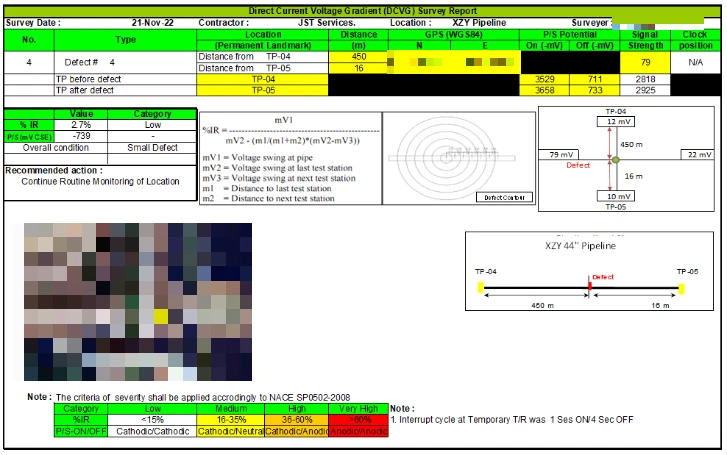
Each defect gets its own record: its position between permanent test posts, GPS coordinates, On/Off pipe-to-soil potentials, signal strength, a severity grade and a recommended action, with a map of the section. You know exactly where to dig, and in which order.
How defects are graded
Severity is graded by %IR, the share of the CP voltage lost at the defect, and by On/Off behaviour, which shows whether the defect is still protected (cathodic) or likely to be corroding (anodic). Our reports apply these criteria under NACE SP0502.
| Category | %IR | Typical action |
|---|---|---|
| LowCathodic / Cathodic | below 15% | Continue routine monitoring |
| MediumCathodic / Neutral | 16–35% | Schedule for repair and check CP levels |
| HighCathodic / Anodic | 36–60% | Prioritise for excavation and coating repair |
| Very highAnodic / Anodic | above 60% | Excavate urgently; active corrosion is likely |
Soil resistivity and pH, measured along the same route
Often carried out during the same visit as DCVG or CIPS, these surveys show how corrosive the ground around your pipeline is, and give the design data for cathodic protection and AC mitigation.
Soil resistivity
Wenner 4-pin method · ASTM G57
Four pins are driven into the ground in a line at equal spacing. Current passes between the outer pins and the voltage drop is read between the inner pins. Repeating at several spacings shows how resistivity changes with depth.
- Lower resistivity means more corrosive soil
- Sets anode bed size and spacing, CP current demand and power supply size
- A major input to AC mitigation design and CP system life
Soil pH
Measured alongside other over-the-line surveys
Shows how acidic the soil is around the pipeline or structure, a useful indicator of how corrosive the environment is.
- Can indicate conditions that favour sulphate-reducing bacteria (SRB)
- Helps decide where extra corrosion control is needed
- Taken on the same visit as the soil resistivity readings
From scoping to a repair plan you can act on
- 01
Scope
Route maps, CP drawings and history reviewed; survey methods and segments agreed.
- 02
Prepare
Permits, right-of-way access and current interrupters installed on rectifiers.
- 03
Survey
Field crews walk the line; readings and defects are GPS-logged every day.
- 04
Analyse
Defects graded, potentials checked against criteria and interference flagged.
- 05
Report
A prioritised dig list, CP recommendations, and GPS coordinates and a map for every defect.
Standards we work to
- AMPP SP0207 – Close-interval potential surveys and DCVG on pipelines
- AMPP SP0502 (NACE SP0502) – Pipeline external corrosion direct assessment
- AMPP SP0169 – Control of external corrosion on underground or submerged metallic piping systems
- ISO 15589-1 / 15589-2 – CP of onshore and offshore pipelines
- ASTM G57 – Soil resistivity by the Wenner four-electrode method
- AMPP TM0109 – Aboveground survey techniques for the evaluation of underground pipeline coating condition
Equipment and partners
 Cath-TechCP survey instruments for DCVG and CIPS
 DairylandDecouplers for AC interference findings
Survey findings that lead straight to the fix
Because JST also designs, installs and maintains cathodic protection, our survey reports don't stop at a list of problems. We can price and deliver the coating repairs, anode beds, rectifier upgrades and AC mitigation the survey calls for.
Industries we serve
Tell us about your pipeline
Send us the route length, location and CP type. A corrosion engineer will review it and come back to you with a recommended survey scope.
Frequently asked questions
DCVG identifies and ranks individual coating defect indications. CIPS assesses how well the cathodic protection system is performing along the entire pipeline. Many operators run them together: CIPS shows where protection is weak, and DCVG shows whether coating defects are the cause.
ACVG uses an AC signal from its own transmitter, so no rectifier, permanent or temporary, is needed. It is less affected by DC interference than DCVG, and it can be run offset from the line where access over the pipe is difficult, such as beside busy roads or in high-voltage corridors.
Your integrity management plan and local regulations set the interval. Most operators repeat CIPS every few years and after major CP changes, and run DCVG as part of direct assessment or before coating rehabilitation.
No. The surveys are carried out above ground while the pipeline stays in service. For CIPS we switch the influencing CP sources on and off together on a timed cycle; the pipe stays protected.
A report with every defect indication GPS-located and graded Low, Medium, High or Very high following NACE SP0502, potential profiles, interference findings and recommended repairs.
Yes. Offshore and river-crossing sections are surveyed by CIPS from a survey boat, with reference electrodes towed in the water directly above the pipeline. Where anodes are welded to the pipe, as on most offshore lines, readings are On potentials only. DCVG and ACVG need ground contact, so they are used on the land sections.
Pipeline current mapping (PCM) puts a low-frequency AC signal on the pipe and measures how much of it remains at points along the route. Current that is lost between two readings has leaked through damaged coating, so PCM shows which sections need attention and gives the pipe position and depth at the same time. ACVG uses an A-frame to pinpoint the exact defect inside a section PCM has flagged. Most programmes run them together: PCM to screen the line, ACVG to locate the digs. PCM is widely used in Thailand but few contractors can offer it.